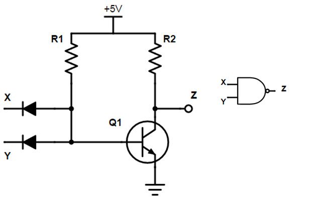
Resistor Transistor Logic Nor Gate
In the schematic given below rdl logic or gate is given in which 2 diodes and 1 pull down resistor are used. But its even better than that because two 1k w resistors in parallel make a 500 w resistor and a 500 w resistor is good enough for our nor.

Solved This Circuit Describes A Resistor Transistor Logic

Introduction To Nor Gate Projectiot123 Technology

Diode Transistor Logic Gates
What is logic nor gate nor gate is a digital logic gate also known as universal gate which gives output 1 only and only when all of its inputs are logic low state 0.

Resistor transistor logic nor gate. We will discuss the basic and most prominent schematic designs in this article including rtl resistor transistor logic mos logic. Pull down resistor means that whenever the diodes are in reversed bias it will pull output voltages down to 0 volts low state 0. For the love of physics walter lewin may 16 2011 duration.
A simple 2 input logic nor gate can be constructed using rtl resistor transistor switches connected together as shown below with the inputs connected directly to the transistor bases. Nor gate is invert of or gate. With two or more base resistors r 3 and r 4 instead of one the inverter becomes a two input rtl nor gate see the figure on the right.
One transistor rtl nor gate. Resistor transistor logic or rtl refers to the obsolete technology for designing and fabricating digital circuits that employ logic gates consisting of nothing but transistors and resistors. This means you dont even have to remove the extra 1k w resistor to build your nor.
Both transistors must be cut off off for an output at q. Diode logic was used extensively in the construction of early computers where semiconductor diodes could replace bulky and costly active vacuum tube elements. Diode logic dl or diode resistor logic drl is the construction of boolean logic gates from diodes.
Resistor diode logic rdl rdl logic comprises resistors and diodes to perform some logic function. This is in fact the pattern for all standard rtl ics. There are several schematic designs used for nor gate.
The nor function is performed at the common collector connection of all transistors which share a single collector load resistor. In resistor diode logic rdl the diode is used as a switching unit. They will make you physics.
The very commonly used ul914 is a dual two input nor gate where each gate is a two transistor version of the circuit to the left. Lectures by walter lewin. However diodes cannot invert any input signal so it is impossible to design nor gate using this logic.
In other words if we connect not gate to the output of or gate that will become nor gate. Csci 255 building logic gates from transistors. Rtl gates are now seldom used if at all in modern digital electronics design because it has several drawbacks such as bulkiness low speed limited fan out and poor noise margin.

Digital Logic Gates Tutorial Logic Gates Truth Table

Vlsi Design Bjt Based Logic Gates

Resistor Transistor Logic

Digital Electronics Logic Gates Basics Tutorial Circuit

Uncovering The Silicon Ml914 Evil Mad Scientist Laboratories

Npn Transistor Nor Gate Circuit Sully Station Technologies

The Bjt Circuit Shown In Figure 2 A Is A Logic N

Resistor Transistor Logic Rtl Ppt Download

Direct Coupled Transistor Logic Dctl Electronics Tutorials

Dictionary Of Electronic And Engineering Terms Rel

Resistor Transistor Logic Rtl

Universal Gates Nand Gate
Comments
Post a Comment